Area Zone
The Power of the Area Zone Command: A Step-by-Step Guide
In today's post, we will walk you through the power of the Area Zone Command and how to effectively use it to add reinforcement to your designs. This function allows you to define regions as input, automatically adding reinforcement to the designated areas while ensuring no reinforcement is placed within the voids (regions within the outer region).
What Does the Area Zone Command Do?
The Area Zone Command is designed to optimize your reinforcement process by recognizing and handling multiple regions within a drawing. When you specify an outer region, the command treats any regions inside it as voids, preventing reinforcement from being placed within them. This is particularly useful in complex designs where you need precise control over where reinforcement should or shouldn’t be applied.
How to Use the Area Zone Command
Follow these simple steps to make the most of this function:
Before you begin, make sure all the outer outlines in your drawing are correctly defined as Regions. You should also add splice lines to indicate where reinforcement will be spliced in the X and Y directions. This step ensures that the command works seamlessly with your drawing and places reinforcements correctly.

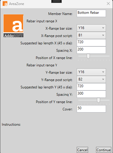
Next, go to the Ribbon and select the Area Zone Command. Once clicked, a popup window will appear. This popup allows you to adjust various values based on your specific project needs, such as spacing, reinforcement sizes, and more. Customize these settings according to your design. See Area Zone Interface Breakdown
Now, select all the regions you want the command to consider for reinforcement. This includes both the outer region (where reinforcement will be applied) and any inner regions (voids) that should be excluded from reinforcement.
After selecting the regions, choose the splice line for the X direction. This defines where the reinforcement will be spliced horizontally. The splice points help you manage overlapping reinforcements and ensure structural integrity. You can have multiple splice lines and are not limited to one.
Finally, select the splice line for the Y direction, which sets the vertical reinforcement splice points. With both the X and Y splice lines in place, your design will have reinforcement perfectly tailored to the layout. You can have multiple splice lines and are not limited to one.
By following these steps, you’ll be able to quickly and efficiently add reinforcement to complex regions in your drawings without worrying about misplacement or voids. This function not only saves time but also increases accuracy in your designs.
Area Zone Interface Breakdown

- Member Name: This field allows the user to specify which member (e.g., "Bottom Rebar") the reinforcement settings will apply to.
Rebar Input Range X
- X-Range bar size: A dropdown for selecting the bar size (e.g., Y16) for the X direction of the rebar.
- X-Range post script: Allows you to select the positional script for the X direction bars, often representing zones or positional attributes (e.g., B1).
- Suggested lap length X (45x dia): The software automatically calculates a lap length based on the selected bar size in the X direction (e.g., 720 mm).
- Spacing X: Specifies the distance between reinforcement bars in the X direction (e.g., 200 mm).
Position of X Range Line
- A slider to adjust the position of the X range line on the graphical interface.
Rebar Input Range Y
- Y-Range bar size: A dropdown for selecting the bar size (e.g., Y16) for the Y direction of the rebar.
- Y-Range post script: Allows selection of the positional script for the Y direction bars (e.g., B2).
- Suggested lap length Y (45x dia): The software calculates a lap length based on the selected bar size in the Y direction (e.g., 720 mm).
- Spacing Y: Specifies the distance between reinforcement bars in the Y direction (e.g., 200 mm).
Position of Y Range Line
- A slider to adjust the position of the Y range line.
Cover
- This field allows the user to input the concrete cover thickness, which is the space between the reinforcement and the outer surface of the concrete (e.g., 50 mm).
Actions
- Cancel: Cancels the operation and closes the dialog.
- Continue: Proceeds with the operation based on the input provided.
