
Create Bar
For advanced users looking to customize reinforcement bar definitions in AddoBar, understanding the bar-list XML file structure is essential. This guide delves deep into the barlist.xml configuration file, located at c:\Addosoft\AddoBar\. We'll explore the XML tree hierarchy, decode shape definitions, and explain key parameters and rationales that drive bar shape customization.
Equipped with an XML-enabled editor like Notepad++, you can tailor variables, shapes, and international reinforcement codes to meet your project's exact specifications. Let's navigate through the essential sections—Codes, Variables, Sizes, and Shapes—to unlock the full potential of your bar-list customization.
Within the XML File, You Will Find the Following Sections:
Codes:
The Codes section defines international reinforcement standards that the bar shapes adhere to. Each code corresponds to a specific country's reinforcement regulations and specifies the guidelines, naming conventions, and other requirements for rebar configurations. This section ensures that each reinforcement shape complies with the relevant regional regulations and standards.
Each container contains the following sub-sections:
- Variables: Defines key parameters such as hook lengths, bending radius, and bar diameters. These are customized for each specific country's reinforcement code and material specifications.
- Sizes: Lists the standard size ranges for reinforcement bars, including the diameter, bending radius, hook lengths, and weight in grams per meter. These sizes are tailored to meet the design and material requirements of each country’s reinforcement standards.
- Shapes: Describes the various shape codes and their corresponding geometric and functional details, including straight and bent bar shapes, dimensions, and grip point locations.
<code name="SANS 282:2011" country="South Africa" />
<code name="BS 8666:2005" country="United Kingdom" />
<code name="BS-8666:2020" country="United Kingdom" />
<code name="BS EN 1992-1-1:2004" country="Europe" />
<code name="BS-8666:2005" country="Europe" />
<code name="BS-8666:2020" country="Europe" />
<code name="AS3600" country="Australia" />
<code name="IS 2502:2013" country="India" />
<code name="RSIC" country="Canada" />
Variables:
The Variables section contains key parameters used in shape-code definitions. These variables are essential for customizing and fine-tuning the geometry and functionality of the reinforcement bars. While some variables are globally defined, others, such as strhook, bnthook, radius, and dia, are derived from the Sizes section where specific values are set based on material types and bar dimensions.
Key variables include:
- strhook: The standard length for straight hooks, which is defined in the Sizes section. It is crucial for ensuring proper anchorage of the bars in the structure.
- bnthook: The standard length for bent hooks, also defined in the Sizes section. This variable is important for creating bent rebar shapes that comply with project requirements.
- radius: The applicable bending radius, defined in the Sizes section. It is key to ensuring that the bar can be bent without breaking or exceeding material limits.
- dia: Represents the bar diameter, defined in the Sizes section. The diameter is critical for calculating load-bearing capacity and compatibility with other design elements.
- PI: The constant value of Pi (π), used in mathematical calculations involving circular or curved shapes.
- dim1–dim5: Customizable dimension variables that are defined and used within shape-code definitions to determine specific dimensions of a bar shape.
These variables offer flexibility and precision, allowing you to adjust bar shapes according to specific material properties and design criteria, ensuring compliance with project standards and regulations.
<variables>
    <symbol name="n" variable="strhook" />
    <symbol name="r" variable="radius" />
    <symbol name="d" variable="dia" />
    <symbol name="h" variable="bnthook" />
    <symbol name="p" variable="PI" />
    <symbol name="xh" variable="bnthook+(radius+dia)*(2-PI)" />
    <symbol name="yh" variable="2*(radius+dia)" />
    <symbol name="N" variable="strhook+2*(radius+dia)-PI*(radius+dia)/2" />
    <symbol name="A" variable="dim1" />
    <symbol name="B" variable="dim2" />
    <symbol name="C" variable="dim3" />
    <symbol name="D" variable="dim4" />
    <symbol name="E" variable="dim5" />
</variables>
Sizes:
The Sizes section defines the standard size ranges for reinforcement bars, linking each size to a specific material type and rebar designator. This section is essential for ensuring that bars meet the dimensional, material, and weight requirements of the project.
Each size entry within the XML file contains critical data for various parameters:
- dia: Defines the bar diameter, which is crucial for determining the load-bearing capacity and compatibility with other structural elements.
- radius: Specifies the applicable bending radius, ensuring that the bar can be bent within permissible limits without failure or cracking.
- bnthook: Establishes the standard length for bent hooks, which is critical for ensuring that bent bars provide the necessary anchorage within the structure.
- strhook: Specifies the standard length for straight hooks, which is essential for the proper anchorage of straight bars in the design.
- weight (grams per meter): Defines the weight of the bar per meter, which is an important factor in the logistics and cost estimation of materials. The weight is calculated based on the bar diameter and material density.
<sizes>
    <typerange symbol="R">
        <size dia="6" radius="12" bnthook="100" strhook="100" weight="222" />
        <size dia="8" radius="16" bnthook="100" strhook="100" weight="395" />
        <size dia="10" radius="20" bnthook="120" strhook="100" weight="617" />
        <size dia="12" radius="24" bnthook="120" strhook="100" weight="888" />
        <size dia="16" radius="32" bnthook="160" strhook="100" weight="1580" />
        <size dia="20" radius="40" bnthook="200" strhook="120" weight="2470" />
        <size dia="25" radius="50" bnthook="260" strhook="160" weight="3850" />
        <size dia="32" radius="64" bnthook="320" strhook="200" weight="6310" />
        <size dia="40" radius="80" bnthook="400" strhook="240" weight="9860" />
    </typerange>

    <typerange symbol="Y">
        ... [Additional sizes for Y omitted for brevity]
    </typerange>
</sizes>
Default:
Specifies the fallback settings used when a matching code is not found in the drawing.
<defaults sc="72" dia="12" symbol="Y" undefined="20" />
Shapes:
The Shapes section is a critical part of the XML configuration, detailing the shape-code definitions used to represent reinforcement bars in the system. These shape-codes define the geometry, grips, and constraints of the bars, ensuring that they meet specific design requirements and are correctly represented in the reinforcement detailing process.
Code Samples
SANS 282:2011 Shape Code 20
<shape code="20">
    <def list="A,0,0,0,a"/>
    <seq ip="0" vl="0" ol="-S|B|S" rv="0-1"/>
    <var def="40*d" max="13e3" min="10*d" red="none" len="A"/>
</shape>
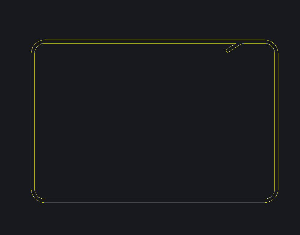
SANS 282:2011 Shape Code 60
<shape code="60">
    <def list="0,N,0,0,f|-1*B-0.1,0,0,0,f|0,-1*A,0,0,f|B,0,0,0,f|0,A-0.1,0,0,f|-1*N,0,0,0,f|-1*N/2,-1*N/3,0,0,a" />
    <seq ip="3" vl="3|2" ol="0|S|T|S|B|S|T|0|0" rv="3-4" />
    <var def="22*d,28*d" max="13e3" min="8*d,8*d" red="none" len="(2*A)+(2*B)+(2*N)-((3/2)*r)-(3*d)" />
</shape>
Linear Propagation of the Reinforcment Bar
<def> container containing a text list defining the linear propagation of the rod. It consists of an arbitrary list of vectors separated with the symbol '|'.
Each vector is defined by 5 comma-separated values:
- Delta x: Moving in the local x-direction. This value may be written as a mathematical function of variables (Polish math notation applies) or a constant.
- Delta y: Moving in the local y-direction.
- Delta z: Moving in the local z-direction (not yet implemented, use
'0'). - Bulge factor: 0 for straight, 0.5 for a 90° bulge, and 1 for 180° degrees. Can be negative.
- Vector code: Alpha codes to manipulate behavior in the vector (see below).
T: Tangent Bulge — Applies bulge on previous, current, and next vector tangents.
b: Normal bulge of a vector.
V: Fillet the end of a vector with the next vector using a specific radius.
f: Fillet with the normal bend.
S: Right offset for double curve lines.
Grip Sequencing Definition
<seq>, defines grip sequencing of the shape. It is important to note when nodes and when vectors are referenced. The node list is 0-based and is always the vector list count plus 1. Vector 0 is defined as node 0 to node 1. The list consists of 4 text values:
- ip: Insertion point number (0-based) as measured from the first vector.
- vl: Vector list, separated with
'|', indicating vectors which should be assigned stretch grips. - ol: Offset list, separated with
'|', defining the offset line. Can be'0','-','S'(side),'T'(top), or'B'(bottom). The first and last values define the side offset of the start and end nodes; the rest apply to the corresponding vector. The list length must be equal to the vector count plus 2. - rv: Rotation vector, defines the vector which will contain the rotation grip based on two node numbers (0-based list).
Variable Dimensions Definition
<var>, defines the 5 variable dimensions of the shape-code. It consists of 5 text values:
- def: Comma-separated list (max length of 5) of the default values for the used dimensions. May be a function of variables as defined earlier.
- max: Comma-separated list (max length of 5) of the maximum allowable length for each dimension (mandatory for bar flipping operation).
- min: Comma-separated list (max length of 5) of the minimum allowable length for each dimension (mandatory for bar flipping operation).
- len: Mathematical formula (Polish notation) of the cut-length. If set to 0, AddoBar will use the geometric centerline of the bar to calculate the cutting length.
Shape-code designators may be alphanumerical. Shape-code designators pre-pended with a '0' will be regarded as unique by the object but not by the schedules. For example, SC 038 and 38 may have different bar definitions, resulting in two unique bar objects, but the scheduler will read both as 38.