
Adding Bars and Ranges
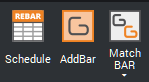
To add a bar to your project, you have two options:
AB_ADDBAR command.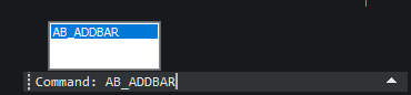
After performing either of these actions, a dialog box will appear.
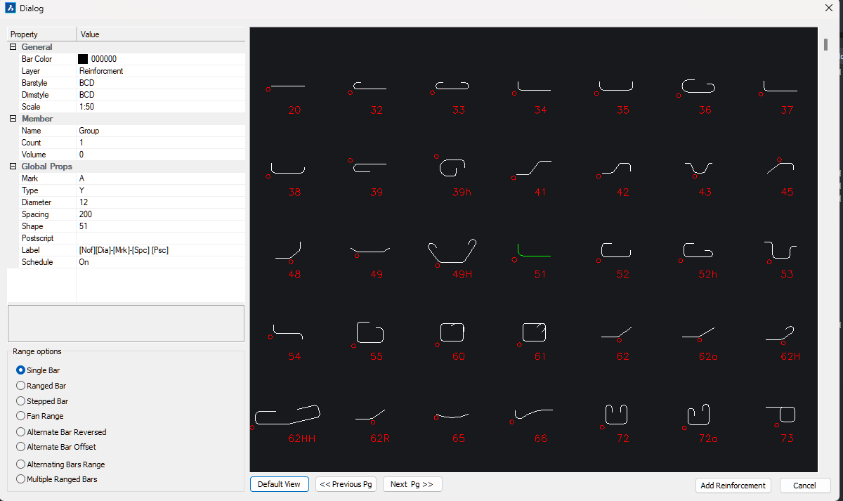
Dialog Box Options for Adding a Bar
In the dialog box that appears when you add a bar, you can adjust various settings to customize its appearance and properties. You can also modify these settings later using the properties palette. Below is a brief description of each option:
General Settings
- Bar Color: Choose the color of the bar to match your design or project requirements.
- Layer: Specify the layer on which the bar will be placed, which affects its visibility and organization in the project.
- Bar Style: Select the style of the bar, such as solid, dashed, or dotted, to fit your project’s specifications.
- Dimstyle: Define the dimension style for the bar, including measurement units and formatting.
- Scale: Adjust the scale of the bar to fit the overall scale of the drawing or project.
Member Settings
- Name: Assign a name to the bar for easy identification and reference.
- Count: Specify the number of bars required in your project.
- Volume: Define the volume of the bar, which may be important for material calculations or analysis.
Global Properties
- Mark: Apply a mark to the bar for tracking or identification purposes.
- Type: Select the type of bar, which could refer to its function or material.
- Diameter: Set the diameter of the bar, if applicable.
- Spacing: Adjust the spacing between bars if multiple bars are used.
- Shape: Define the shape of the bar, such as round or square.
- PostScript: Include any PostScript information if necessary for documentation or printing.
- Label: Add a label to the bar for additional information or identification.
- Schedule: Choose whether the bar should be included in the project schedule or not.
Range Options for Bars
- Single Bar: Select this option to create a single bar with a fixed range, ideal for simple applications where only one bar is needed.
- Range Bar: This option allows you to define a range for the bar, which can be useful for representing data or measurements over a specific interval.
- Stepped Bar: Choose the stepped bar option to create a bar with discrete steps, making it suitable for showing data with distinct intervals or stages.
- Fan Range: The fan range option creates a bar that spreads out in a fan-like shape, useful for visualizing data with a radial distribution.
- Alternate Bar Reverse: Use this setting to alternate bars in a reversed order, which can be helpful for distinguishing between different data sets or categories.
- Alternate Bar Offset: This option allows you to offset alternate bars, creating a staggered appearance. It is useful for enhancing visual differentiation between bars.
- Alternating Bars Range: Select this option to set up bars that alternate in appearance or data range, providing a clear visual distinction between different segments or values.
- Multiple Bars Range: This setting enables the creation of multiple bars within a defined range, which is ideal for displaying a series of related data points or comparisons.
Inserting a Single Bar
To insert a single bar into your project, follow these steps:
- Choose a bar from the shape code list.
- Adjust the bar color and other relevant settings as needed.
- Click the Add Reinforcement button.
- Follow the prompts to select the bar cover points.
- Click to add the points for the leader. Note that the leader points will continue to be added until you press
ESCto end the function.
Make sure to complete the process by pressing ESC when you are finished adding leader points.
Inserting a Range Bar
To insert a range bar into your project, follow these steps:
- Choose a bar from the shape code list.
- Adjust the bar color and other relevant settings as needed.
- Click the Add Reinforcement button.
- Follow the prompts to select the bar cover points.
- Follow the prompts to select the Range Start and End points.
- Click to add the points for the leader. Note that the leader points will continue to be added until you press
ESCto end the command.
Make sure to complete the process by pressing ESC when you are finished adding leader points.
Inserting a Stepped Bar
To insert a stepped bar into your project, follow these steps:
- Choose a bar from the shape code list.
- Adjust the bar color and other relevant settings as needed.
- Click the Add Reinforcement button.
- Follow the prompts to select the bar cover points; this will be needed for both the start and end of the bar.
- Follow the prompts to select the Range Start and End points for the stepped bar.
- Click to add the points for the leader. The leader points will continue to be added until you press
ESCto end the command.
Make sure to complete the process by pressing ESC when you are finished adding leader points.
Inserting a Fan Range Bar
To insert a fan range bar into your project, follow these steps:
- Choose a bar from the shape code list.
- Adjust the bar color and other relevant settings as needed.
- Click the Add Reinforcement button.
- Follow the prompts to select the bar cover points.
- After placing the bar, you will be prompted to pick the center point of the arc you want to use.
- Select the position for the range line as prompted.
- Pick the Range Start and End points for the fan range.
- Click to add the points for the leader. Note that the leader points will continue to be added until you press
ESCto end the command.
Important: The fan range uses degrees (°) for spacing, not millimeters (mm). To convert the spacing to degrees, use the following formula:
degrees = (spacing / radius) * (180 / π)
Millimeters to Degrees Conversion Tool
Enter the spacing in millimeters and the radius to convert it to degrees:
Inserting an Alternate Bar Reversed Range
To insert an alternate bar reversed range into your project, follow these steps:
- Choose a bar from the shape code list.
- Adjust the bar color and other relevant settings as needed.
- Click the Add Reinforcement button.
- Follow the prompts to select the bar cover points for both sides of the bar.
- Follow the prompts to select the Range Start and End points.
- Click to add the points for the leader. Note that the leader points will continue to be added until you press
ESCto end the command.
Make sure to complete the selection process by pressing ESC when you are finished adding leader points.
Inserting Multiple Range Lines
To insert multiple range lines into your project, follow these steps:
- Choose a bar from the shape code list.
- Adjust the bar color and other relevant settings as needed.
- Click the Add Reinforcement button.
- Follow the prompts to select the bar cover points.
- Next, follow the prompts to select the Range Start and End points. You will be asked to continue adding range lines until you no longer need any more. After adding the final range line, press
ESCto start adding leader points. - Click to add the points for the leader. Note that the leader points will continue to be added until you press
ESCto end the command.
Ensure you press ESC to finish the leader point selection process and complete the insertion.